Acrylonitrile Butadiene Styrene (ABS) is a widely used thermoplastic known for its toughness, impact resistance, and ease of processing. However, one limitation of standard ABS resin is its relatively low heat resistance, which can restrict its application in high-temperature environments. For manufacturers and designers looking to enhance ABS performance, N-phenylmaleimide (N-PMI) has emerged as a highly effective solution.


1.Understanding ABS Heat Resistance Challenges
ABS is composed of three monomers: acrylonitrile, butadiene, and styrene. While butadiene imparts toughness, it also lowers thermal stability. Standard ABS can soften at temperatures around 90–100°C, limiting its use in automotive components, electrical housings, or other heat-demanding applications. Enhancing heat resistance without compromising mechanical properties is therefore a critical objective.
2.Role of N-Phenylmaleimide in ABS
N-phenylmaleimide, especially the high-purity variant produced by Yangchen Tech, is an innovative modifier for ABS resin. Its unique chemical structure enables it to copolymerize with styrene and acrylonitrile, forming ABS-graft copolymers with significantly improved thermal performance.
Basic Infomation
| Chemical Structure |  |
| Chemical Formula | C10H7NO2 |
| Molecular Weight | 173.16 |
| CAS No. | 941-69-5 |
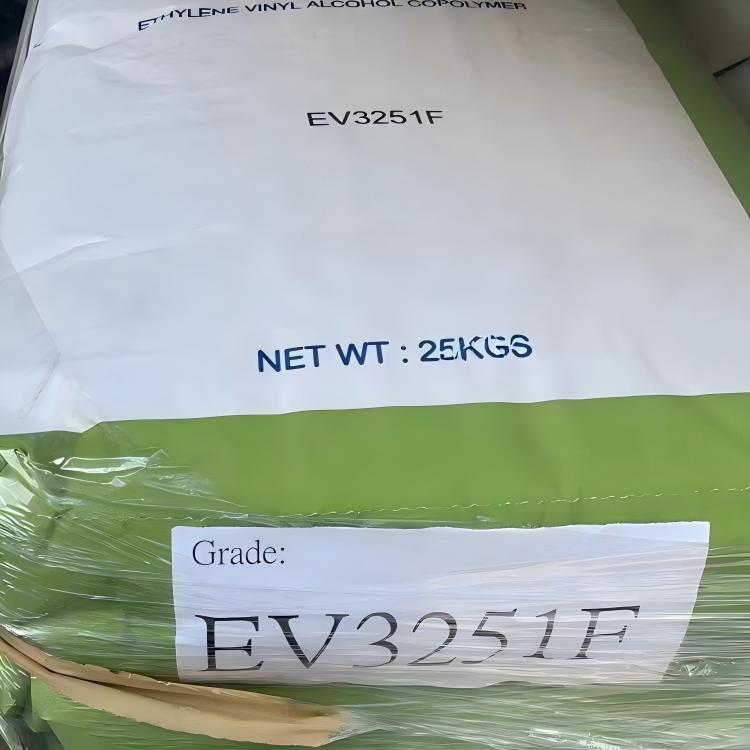
| Packing Type | Paper bag (20 kg) |
3.Key Advantages of N-Phenylmaleimide from Yangchen Tech
-
Enhanced Heat Resistance
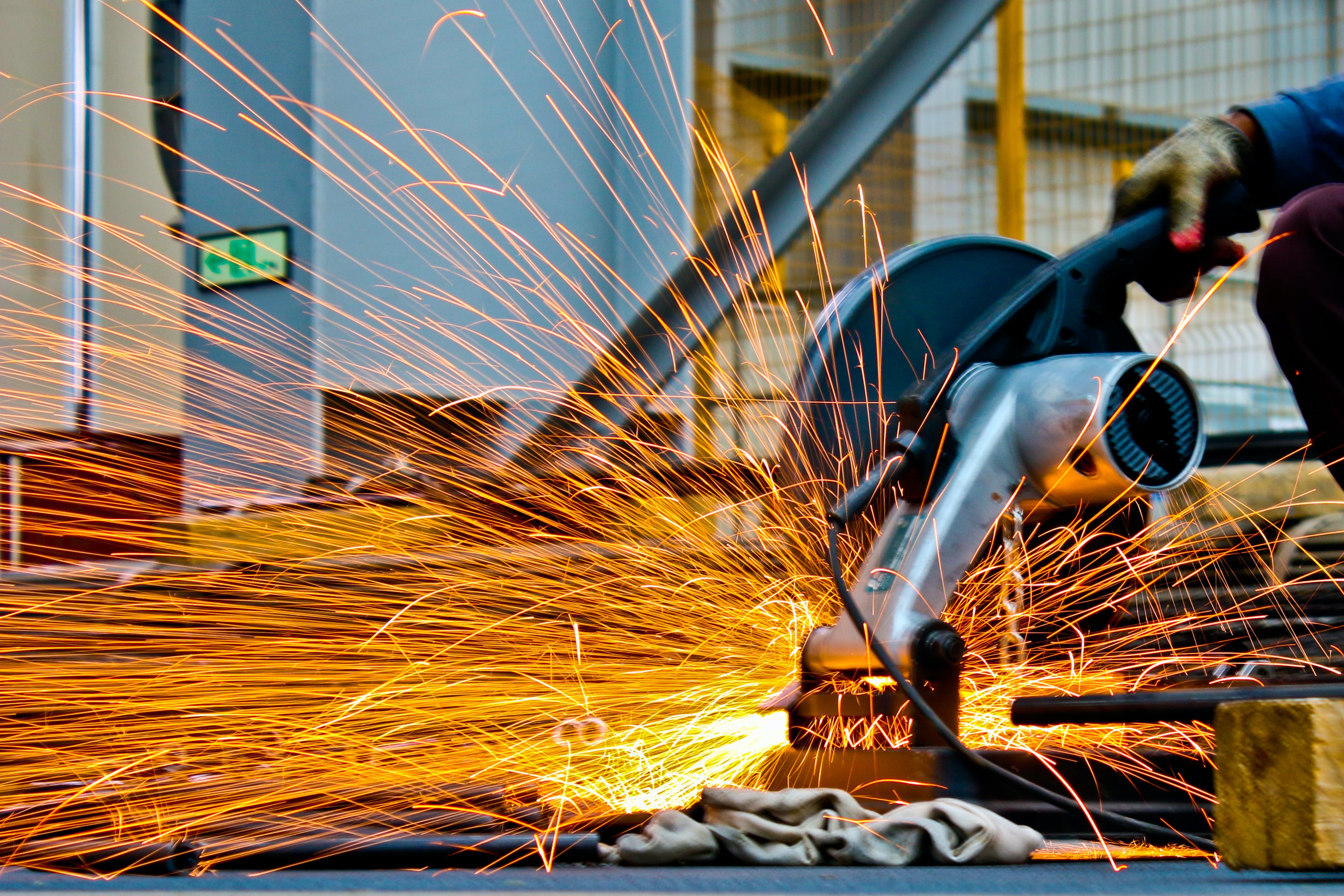
Incorporating N-PMI increases the glass transition temperature (Tg) of ABS, allowing the resin to maintain structural integrity at higher temperatures. This is particularly valuable for applications like automotive parts, electrical enclosures, and high-performance consumer products. -
Superior Solubility
Yangchen Tech’s N-phenylmaleimide offers excellent solubility in styrene and other co-monomers, ensuring uniform dispersion in the polymer matrix. This results in consistent performance and prevents weak spots that can compromise thermal resistance. -
High Purity and Reliability
With a purity of 99%, Yangchen Tech’s N-PMI guarantees minimal impurities, reducing the risk of unwanted side reactions during polymerization. This ensures stable processing and predictable performance outcomes for manufacturers. -
Customizable for Various Applications
Yangchen Tech provides tailored N-PMI solutions to meet different heat-resistance targets, enabling manufacturers to optimize ABS formulations for specific industrial needs.
4.How to Incorporate N-PMI into ABS
To enhance ABS heat resistance, N-phenylmaleimide can be integrated via:
-
Bulk or Solution Polymerization: N-PMI is added to the monomer mixture during ABS synthesis, enabling it to copolymerize efficiently.
-
Graft Copolymerization: N-PMI is grafted onto ABS chains, enhancing thermal stability without compromising mechanical strength.
-
Reactive Blending: Existing ABS resins can be blended with N-PMI under controlled conditions to improve high-temperature performance.
The key is ensuring even dispersion and correct reaction conditions, which Yangchen Tech supports with technical guidance and high-quality products.
5.Why Choose Yangchen Tech for N-Phenylmaleimide
As a leading manufacturer of maleimide derivatives, Yangchen Tech specializes in producing high-performance N-PMI suitable for ABS modification. Their expertise ensures:
-
Consistent quality and high purity
-
Excellent solubility for uniform ABS incorporation
-
Technical support for optimizing heat-resistant ABS formulations
-
Global supply with customization options
For manufacturers seeking to push the boundaries of ABS resin applications, enhancing heat resistance is crucial. N-phenylmaleimide from Yangchen Tech provides an effective, reliable, and high-performance solution. By incorporating N-PMI into ABS formulations, products can withstand higher temperatures while maintaining structural integrity and durability.
Whether you are developing automotive components, electrical housings, or consumer electronics, N-phenylmaleimide offers a pathway to superior thermal performance and product reliability.
--------------占位---------------